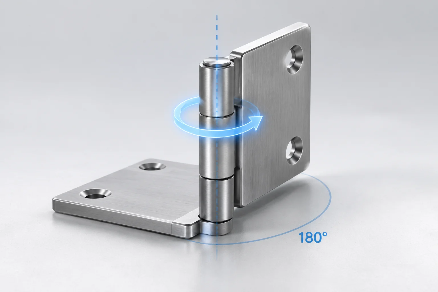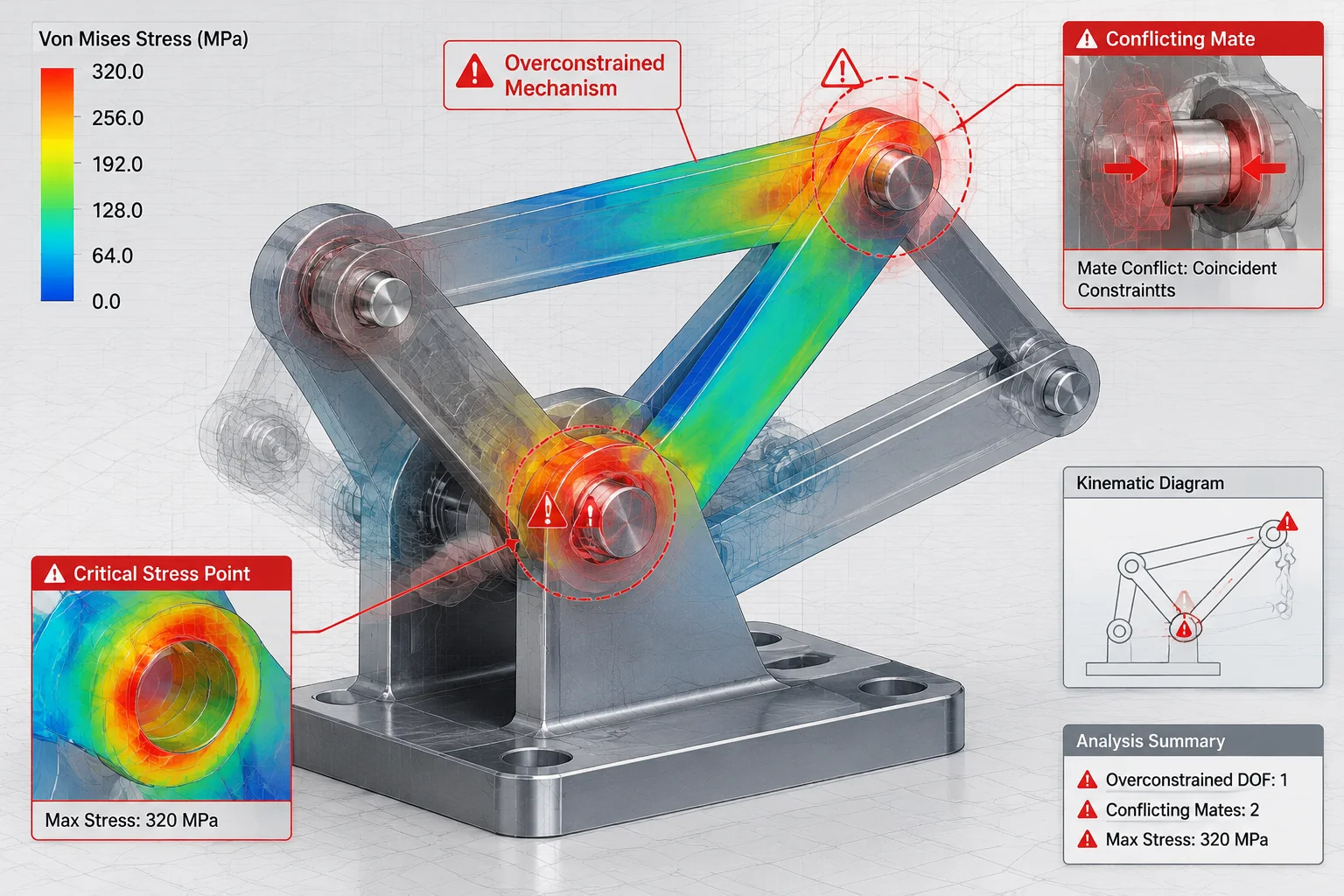
Core Symptoms of Unstable Part Motion
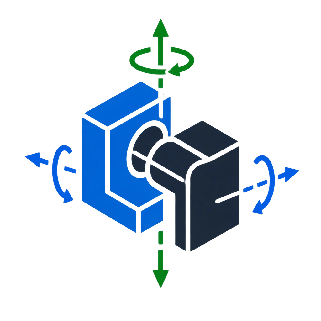
- A concentric mate preserves axial rotation; touching a face with your cursor can spin parts without warning.
- Sub-assemblies set to flexible often pass unconstrained degrees of freedom straight into top-level joints.
- Rebuilding after minor geometry edits can flip parallel or tangent mate solutions into alternate stable positions.
- Mating downstream parts to moving hardware creates cascading spatial drift across the entire model tree.
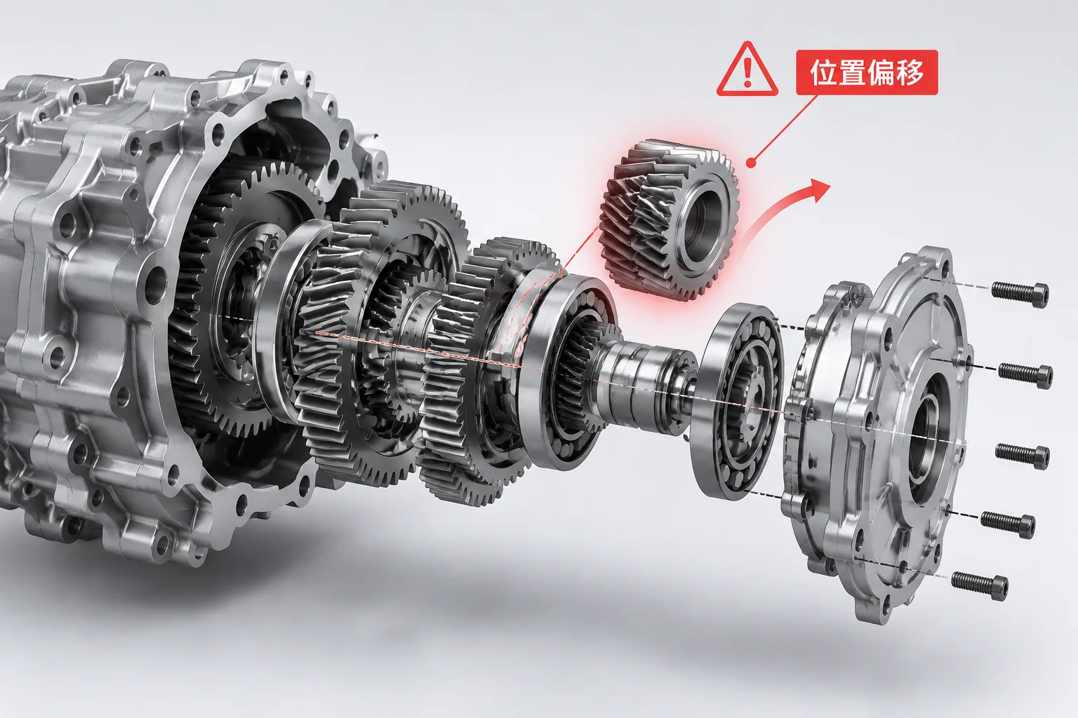
Why Rigid Assemblies Still Permit Unintended Motion
Assembly designers often place coincident or concentric mates expecting parts to lock securely in space. A concentric mate locks only two translational degrees of freedom, leaving the component free to rotate around its central centerline. When another user opens the assembly or performs a casual rebuild, a stray mouse drag displaces the part or exposes floating internal linkages.
True rigidity requires constraining every single rotational and translational axis unless purposeful kinematic motion is desired. A component drifting off its nominal station usually reveals a mate referencing a chamfer, an offset face, or a flexible sub-assembly whose internal components still possess unresolved planar movement.
An unexpected shift in a CAD model is rarely a software glitch; it is an open mathematical degree of freedom finding an alternate equilibrium.
Systematic Isolation of the Slipping Element
Locating the exact mate responsible for unintentional movement requires a disciplined troubleshooting approach rather than randomly adding lock constraints:
- Test Freedom via Drag: Click and drag the suspect part directly in the graphics area to observe which axis slides or rotates freely without triggering mate errors.
- Inspect Feature Tree Prefixes: Look for the minus sign (-) before the component name, indicating that the solver still detects at least one unconstrained degree of freedom.
- Trace Sub-Assembly Flexibility: Verify whether parent sub-assemblies are set to flexible or rigid, as internal motion propagates outward and causes phantom movement at top levels.
Locking Geometry to Primary Reference Planes
To ensure components remain rock-solid through complex revisions, ground secondary parts against primary reference planes or stable skeleton sketches instead of transient cosmetic faces. Reference surfaces created by machining cuts or drafts can shift after upstream design changes, triggering mate flips and unintended displacement. By anchoring rotation against the primary assembly planes, mechanical models withstand revisions without mysterious drift.