Core Checklist Principles for Stable Mates
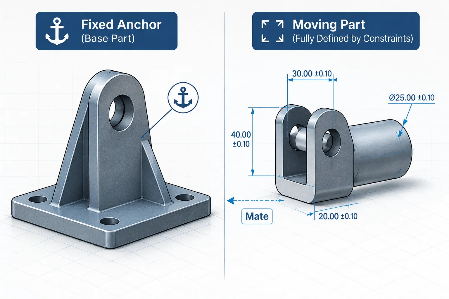
- Fix only one reference component per subassembly to establish an unambiguous ground coordinate system.
- Prefer primary datum planes over volatile chamfers or draft faces to ensure resilient mating surfaces.
- Separate motion studies from static subassemblies to avoid circular recalculations during revisions.
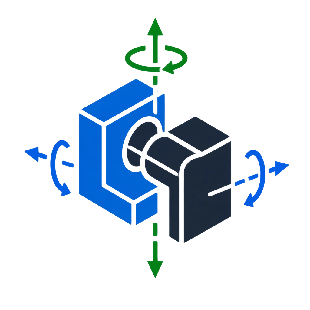
- Audit unresolved rotational freedom on concentric fasteners systematically to prevent solve slowdowns.

Pre-Mate Geometry & Grounding Verification
Before applying a single mate in an assembly, engineers must confirm that the base chassis or mounting plate aligns precisely with the global origin. An ungrounded initial part introduces floating coordinate shifts that cascade silently across downstream parts. When two separate base components both claim fixed status through arbitrary mates, solve engines expend unnecessary cycles reconciling tiny numerical discrepancies.
Evaluate the feature trees of individual components for unstable upstream references. Chamfers, cosmetic fillets, and draft angles undergo frequent design changes; anchoring primary constraints directly to these secondary details almost guarantees broken mates during subsequent engineering revisions. Clean planes and dedicated axis features provide durable landing surfaces.
A dependable constraint tree does not happen by accident; it requires disciplined reference choices and strict degree-of-freedom auditing before any part drawing is approved.
The Six Essential DOF Checkpoints
Executing a standardized checklist ensures no subtle degrees of freedom slip into production models uninspected. Run through these core criteria on every modified subassembly before committing to product lifecycle management systems:
- Origin & Ground Alignment: Confirm exactly one anchored base component mated directly to the main assembly planes.
- Concentric Rotation Lock: Lock unnecessary spin on standard hardware or explicitly assign a parallel relationship.
- Hierarchical Subassembly Nesting: Solve kinematic chains inside flexible subassemblies rather than cluttering top-level trees.
Post-Revision Diagnostic Protocol
After modifying dimensions or swapping revision levels, rebuild the entire assembly with forced regeneration enabled. Look closely for yellow warning glyphs and silent degree-of-freedom deviations. When an update flags a warning, isolate the affected mate group immediately instead of stacking supplementary mates on top of conflicted mates. Stacking temporary mates turns manageable errors into systemic rebuild failures.