Typical Revision Pitfalls & Quick Remediation
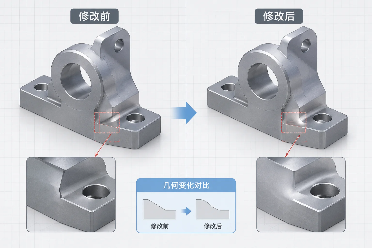
- Feature modifications often alter internal edge and face IDs, causing downstream assembly mates to lose their geometric anchors.
- Suppressing recently modified components isolates whether the solver failure originates from a single part or a chain reaction.
- Replacing dangling topological selections with primary coordinate planes and central axes prevents recurrent rebuild breaks.
- Always inspect dynamic subassemblies for accidental overconstraints when external face dimensions shift during revisions.

Isolating Solver Conflicts and Dangling References
When an upstream part revision enters a top-level assembly, the rebuild process frequently triggers a cascade of yellow warning triangles and red mate errors. Rather than randomly modifying mates, an engineer should roll back the assembly tree or isolate the revised part to assess where topology broke.
Most rebuild errors stem from persistent identifier reassignments inside CAD kernels. Even subtle changes, like reordering a fillet before a cut-extrude or changing a profile vertex, create newly indexed surface faces. The assembly solver cannot find the previous face ID, leaving the mate dangling in an unresolved mathematical state.
Never patch an assembly by layering redundant coincident mates over broken constraints. Identify the missing topological reference and redirect it to a persistent datum plane.
Analyzing Why Reference Changes Trigger Cascades
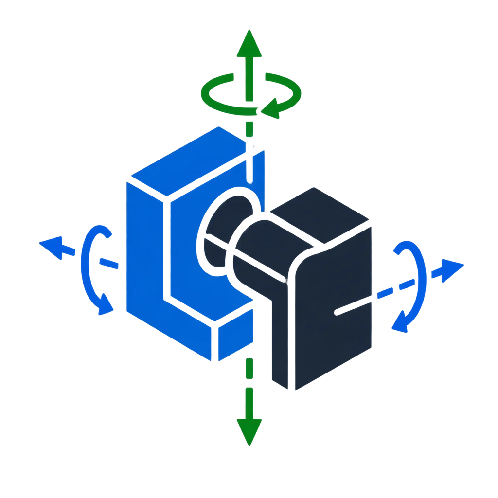
A revision alters parts in three distinct dimensions: geometric displacement, topological regeneration, and kinetic interference. When one component moves unexpectedly, troubleshooting requires isolating each factor sequentially:
- Dangling Reference Entities: Faces or edges consumed or renamed during part remodeling, leaving coincident and concentric mates disconnected.
- Overconstraint Contradictions: Dimensional growth across a housing or bracket forcing parallel faces past their allowable solver tolerances.
- Unintentional Kinematic Freedom: Accidental removal of an anti-rotation mate during cleanup, allowing a shaft or bushing to spin freely without warning.
Restoring Solver Stability and Verifying Degrees of Freedom
Once broken constraints are pinpointed, re-attach each reference using the Mate Diagnostic tool or manual entity re-selection. Best practice dictates replacing fragile cosmetic surface faces with reference datums, assembly sketches, or cylindrical centerlines. Once the assembly rebuilds without errors, drag each unpinned component to verify that degrees of freedom match initial mechanical intent rather than settling into unconstrained drift.