Core Engineering Distinctions
- A fixed part locks its local coordinate system to the top-level assembly coordinate system, bypassing the constraint solver entirely.
- Fully defined components require mate calculation passes during rebuild, maintaining deliberate kinematic ties to neighboring geometry.
- Modifying mounting patterns or reference faces dynamically repositions fully defined parts but leaves fixed components stranded in space.
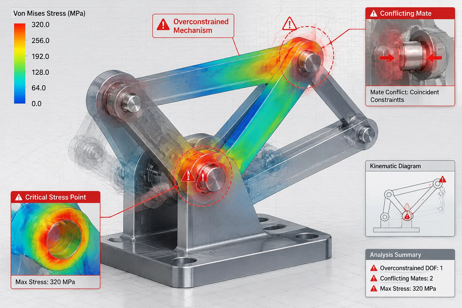
- Fixing intermediate links masks over-constrained conditions and prevents subassemblies from exhibiting flexible mechanism movement.
Coordinate Anchoring vs Geometric Constraint Networks
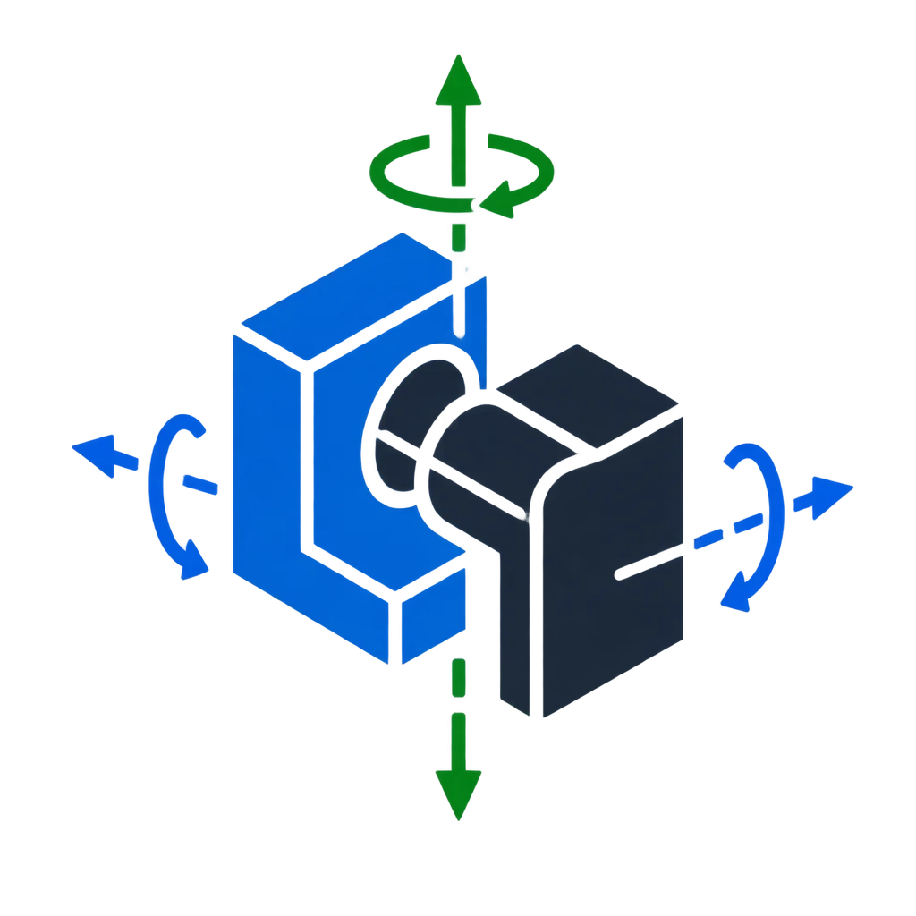
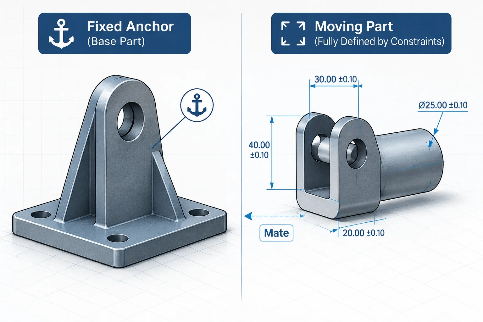
When an engineer assigns a fixed state to a component, the CAD engine applies a static spatial transformation matrix that freezes all six degrees of freedom relative to the global assembly coordinate origin. The component does not evaluate faces, cylindrical bores, or datum references from surrounding parts. It simply holds its position in virtual space, isolated from the geometric changes occurring throughout the rest of the model hierarchy.
By contrast, a fully defined component achieves zero degrees of freedom strictly through explicit geometric relationships such as coincident planes, concentric axes, and distance offsets. While both components appear immovable when dragged with the cursor, the underlying mathematical architecture is fundamentally different. A fully defined part understands its mechanical context, meaning it moves adaptively whenever adjacent structural geometry undergoes revision.
Fixing a part is not an advanced mating technique; it is a static spatial override that severs mechanical intent from the assembly tree.
Solver Execution and Upstream Modification Vulnerabilities
In complex parametric machinery, relying on fixed components instead of proper kinematic mates introduces subtle failure modes that can silently undermine downstream fabrication drawings and simulation models:
- Rebuild Performance: The assembly solver skips matrix calculations for fixed components, whereas fully defined networks must evaluate iterative equations during every geometry update.
- Parametric Revision Resilience: If an underlying chassis thickness increases by five millimeters, fully defined mounting brackets shift in tandem, while fixed brackets remain frozen and cause physical interference.
- Mechanism Flexibility: Subassemblies imported with internally fixed components fail to articulate when inserted as flexible subassemblies inside higher-level mechanical models.
Best Practices for Assembly Grounding and Alignment
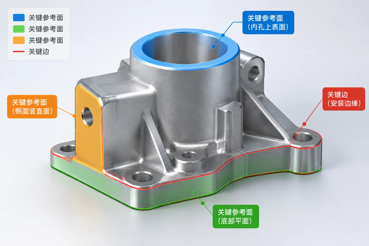
Engineering standards dictate that only the primary foundation component should be grounded in an assembly. Rather than leaving the base part arbitrarily fixed in place, best practice calls for aligning the part default planes directly to the assembly reference planes using coincident relationships. Every subsequent bracket, shaft, fastener, and housing should achieve full definition solely through intentional geometric mates that faithfully represent actual mechanical assembly methods.