Core Takeaways on Coincident & Concentric Assembly Mates
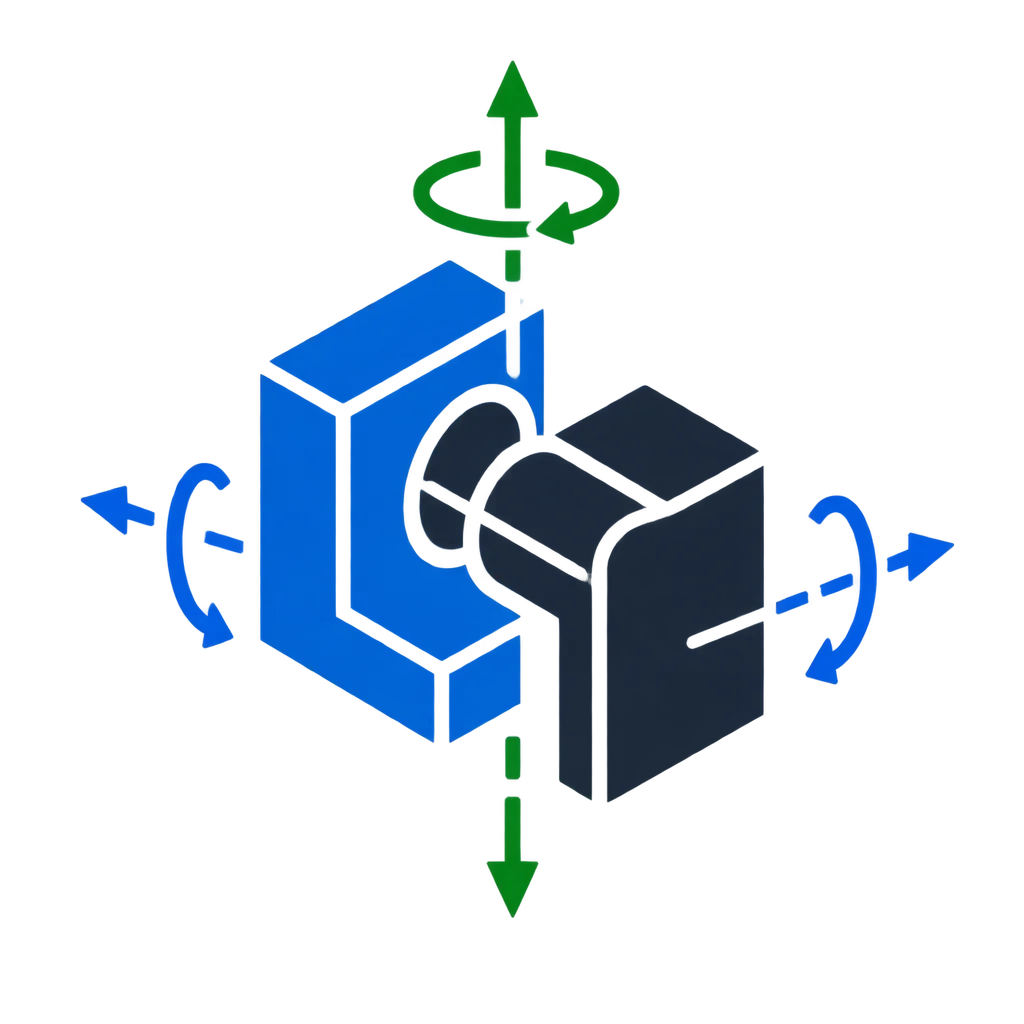
- Concentric mates strictly align rotational centerlines, restricting two radial translation axes while leaving axial travel and rotational spin free.
- Coincident mates force entities into an identical infinite plane, locking one normal translation and two out-of-plane tilting rotations.
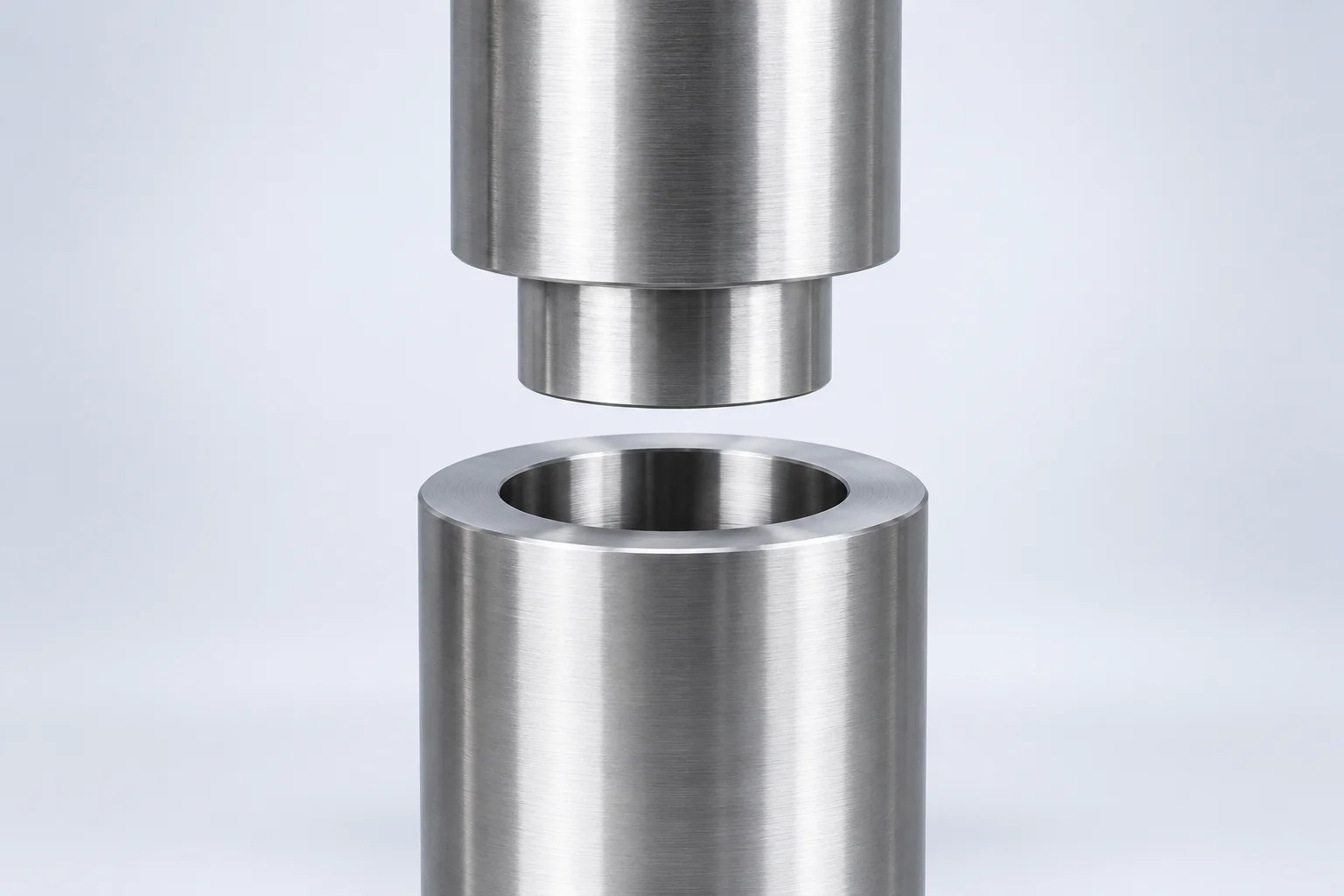
- Pairing one concentric cylinder mate with one planar coincident face contact establishes a reliable cylindrical pin-in-hole revolute joint.
- Applying coincident mates directly between cylindrical axes and planar faces leads to over-constraining errors during model regeneration.
Mechanical Distinction Between Coincident and Concentric Mates
In parametric mechanical assemblies, concentric and coincident mates serve two fundamentally distinct geometric purposes. A concentric relationship enforces strict axial collinearity between the rotational axes of two cylindrical, conical, or spherical elements. By aligning the central vector lines across 3D space, this mate removes two radial translational degrees of freedom while deliberately leaving axial travel along the shaft and continuous 360-degree rotation unconstrained.
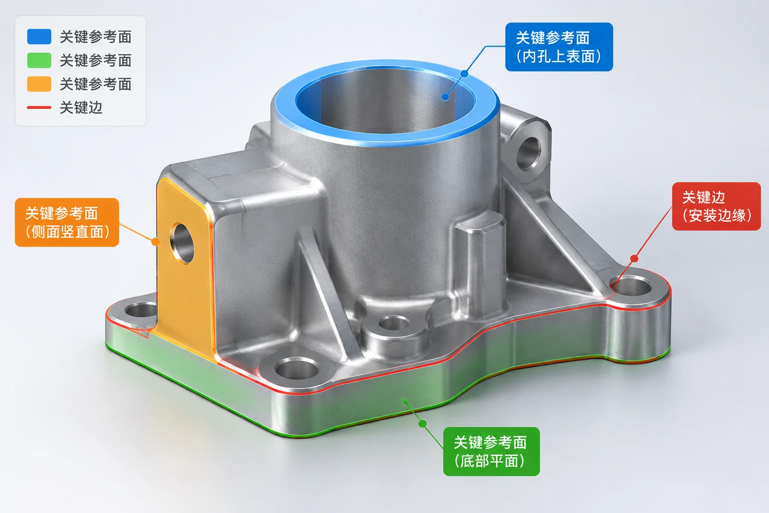
A coincident mate establishes direct coplanar positioning between two surfaces or spatial references. When placed between two planar faces, it binds them to the exact same infinite mathematical plane. This locks one translation perpendicular to the face alongside two rotational axes lying parallel to that plane. Confusion occurs when modelers attempt to use coincident relationships across circular features, accidentally stripping rotational motion or forcing unexpected surface tangential alignments.
Deciding between a concentric axis lock and a coincident planar seat dictates whether your CAD assembly functions as a dynamic kinetic mechanism or locks into an inflexible virtual weldment.
Tracking Degrees of Freedom in Pin-and-Bore Geometry
Every free component inside a 3D assembly starts with six degrees of freedom: three spatial translations along the primary orthogonal axes and three spatial rotations around them. Choosing the appropriate relationship depends on isolating the exact mechanical freedom required for your joint:
- Pure Concentric Relationship: Eliminates radial translations along the X and Y coordinates of the bore, keeping sliding travel along the Z vector and rotation around the central axis completely free.
- Planar Coincident Relationship: Restricts translation along the normal axis and halts tilting about both perpendicular axes, leaving two planar sliding movements and one normal face rotation active.
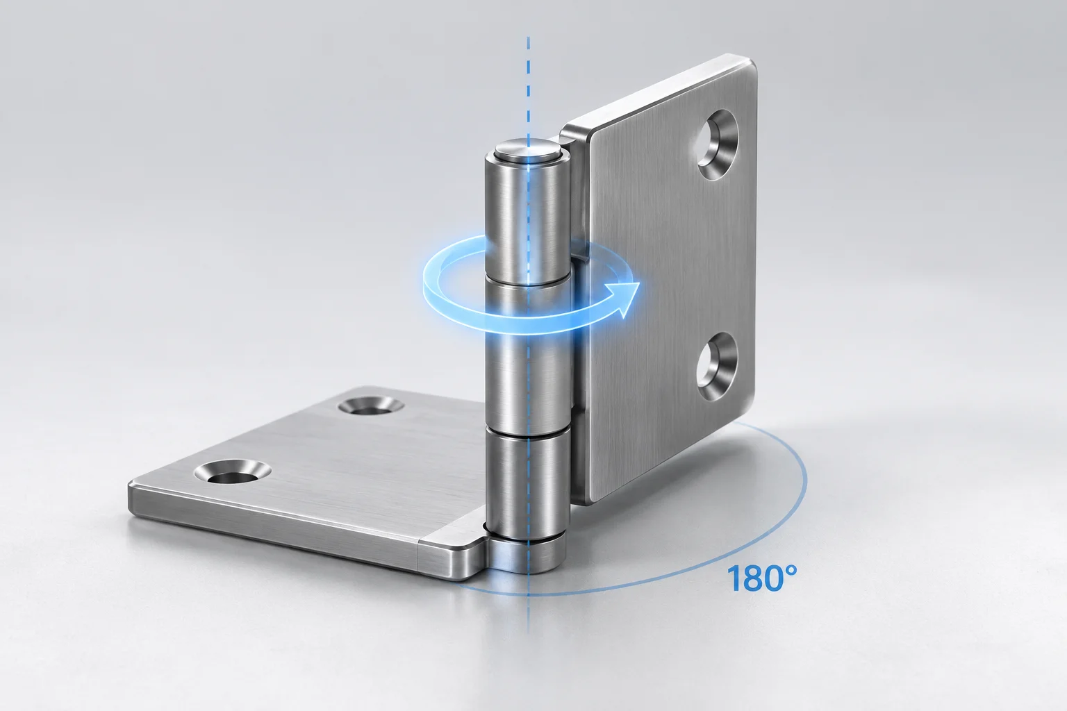
- Combined Revolute Joint: Merging one concentric mate with one coincident shoulder mate leaves precisely one rotational degree of freedom, reproducing standard physical hinges and idler shafts without redundancy.
Practical Strategies to Avoid Solver Conflicts and Rigidity
A widespread pitfall in bolt hole circles and multi-pin mounts is assigning secondary concentric mates to multiple parallel holes while simultaneously locking flat surfaces with coincident mates. If subsequent manufacturing tolerances or bolt-circle revisions introduce even a 0.002 mm variance between pitch centers, the assembly solver encounters conflicting coordinate targets and reports severe overconstraint errors. To keep models predictable, align the primary locator with a concentric mate, establish depth through a coincident planar contact, and resolve rotational orientation using an angular limit or parallel reference rather than a second rigid concentric lock.