Core Rules for Selecting Robust CAD References
- Default origin planes and reference axes remain completely immune to geometric splits caused by fillets, rounds, or drafting modifications.
- Edges and tangent silhouette curves frequently re-index their internal IDs during upstream model regenerations, breaking mates silently.
- Functional machining contact pads should anchor kinetic constraints rather than decorative cosmetic covers or clearance enclosures.
- Decoupling sub-assembly references through top-down layout skeletons prevents recursive circular dependencies during major redesigns.
The Fragility of Entity IDs Under Model Revision
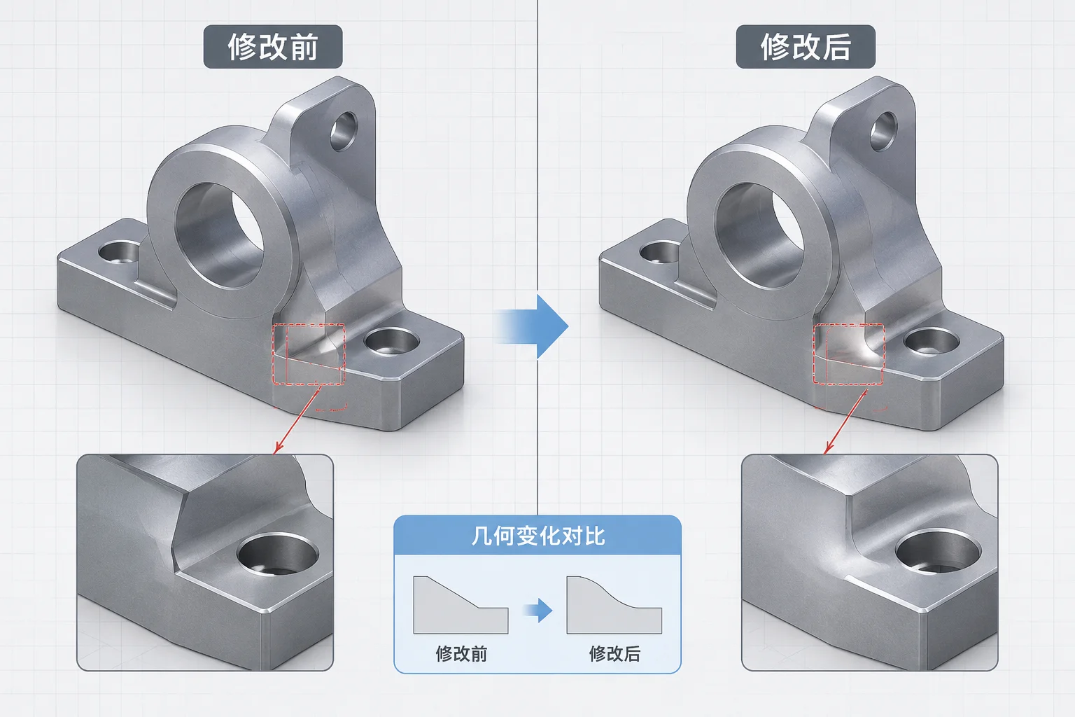
Geometric modeling kernels track individual faces, vertices, and edges through internal tracking tags known as persistent entity IDs. When an engineer clicks an arbitrary flat face to apply a coincident mate, the assembly file records that exact underlying ID tag. If an upstream feature later divides that face with a slot, applies a chamfer, or introduces a draft angle, the kernel drops the previous ID and generates new topological tags for the resulting sub-faces.
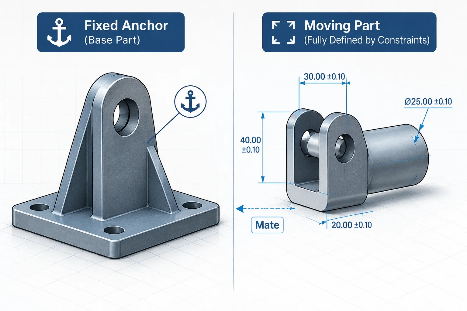
When the assembly tree attempts to resolve its mate solver, the missing reference triggers the familiar yellow warning triangle or red error status. The mate is not fundamentally wrong in its kinematic logic, but its reference vanished from the database. Selecting persistent geometry—such as standard datum reference planes, cylindrical axis centerlines, or dedicated top-down skeleton sketches—insulates your sub-assemblies from routine part-level geometry refinements.
A mate anchored to an exterior finished face will inevitably break during manufacturing revisions. Anchoring to invariant functional planes ensures your assembly architecture outlives every product design tweak.
Evaluating Reference Types from Highest to Lowest Stability
Establishing deliberate CAD modeling conventions across engineering teams requires ranking reference choices. By systematically favoring invariant entities over secondary cosmetic surfaces, assemblies experience dramatic reductions in mate solver regeneration overhead and downstream drawing breakdown:
- Default Datum Reference Planes: Base Front, Top, and Right planes reside at the root of the feature tree and remain indestructible, providing zero rebuild overhead even if complex bodies are suppressed.
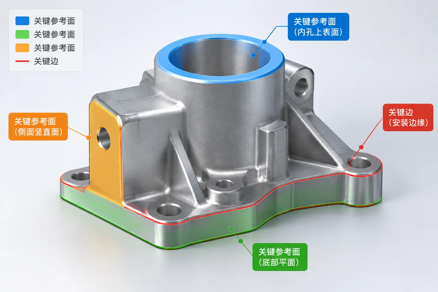
- Machined Primary Contact Pads: Flat seating surfaces and main bearing bore centers represent functional real-world contact and rarely vanish during manufacturing cost-reduction exercises.
- Pattern Driven Centerlines & Layout Skeletons: Dedicated sketch skeletons define kinematic pivot lengths and bolt circles independently of changing casting thicknesses or external sheet metal bends.
Auditing Constraint Trees to Eliminate Dangling Pointers
Periodic constraint health audits prevent unstable reference chains from accumulating unnoticed. Engineers should inspect the mate folder for orphan entities after any revision, replace edge-to-face contacts with plane-to-cylinder relationships, and verify that sub-assemblies are mated back to primary structural bases rather than daisy-chained through peripheral hardware like washers or fastener heads.