Core Mechanical Takeaways
- Translating a reference face adjusts coordinate transformations for all downstream parts linked to that surface.
- Angular variations on planar faces alter perpendicular vector alignments across entire mated subassembly chains.
- Patterned fasteners and secondary brackets rebuild in shifted coordinates, silently reducing critical operating clearances.
- Switching from machined face references to primary datum planes protects constraint chains from unpredicted drift.
Kinematic Recalculation Across the Assembly Tree
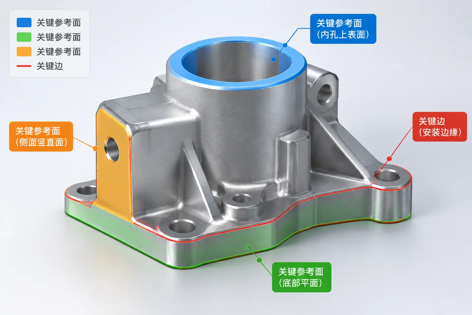
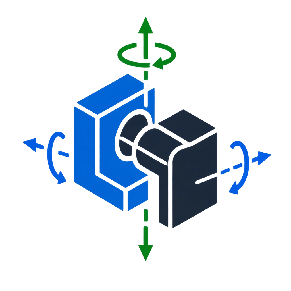
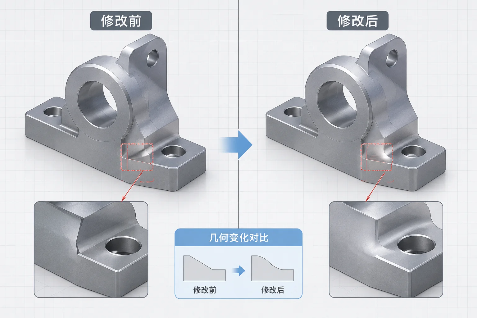
Modifying the position or angle of a reference face triggers an immediate recalculation across the entire parametric constraint tree. Assembly mate solvers treat geometric faces as mathematical definitions with precise origin coordinates and outward normal vectors. Shifting a face translationally forces the solver to recompute transformation matrices for every component directly or indirectly tied to that boundary.
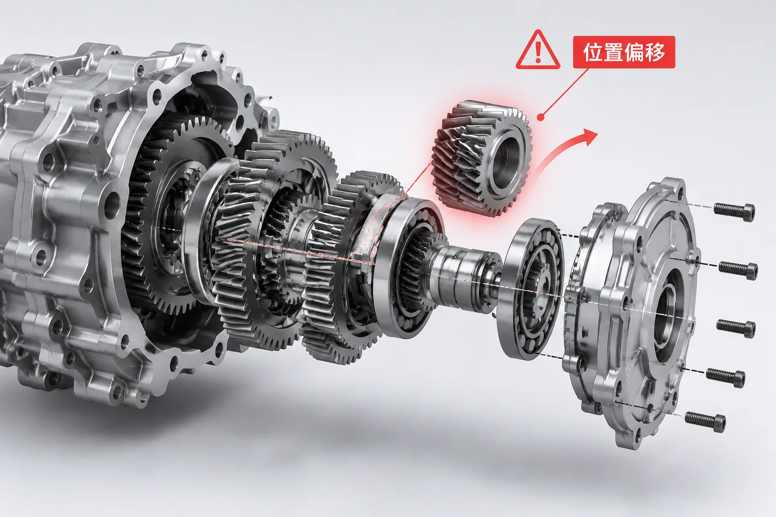
If a mounted bracket possesses an unconstrained rotational degree of freedom, the solver naturally resolves the offset by sliding or pivoting the component along its least constrained pathway. This automatic mathematical accommodation often appears stable at first glance, but it invariably alters relative positioning across adjacent subassemblies.
A modest one-millimeter shift on a base reference face can propagate into a multi-degree angular drift across a secondary mechanical linkage.
Hidden Displacement and Clearance Envelope Compression
Geometric revisions frequently introduce silent design conflicts without generating explicit mate error flags. While the constraint solver satisfies the requested coincident or parallel mates, surrounding spatial relationships suffer unexpected alterations:
- Clearance Envelope Compression: Operating gaps between moving linkages and static structural ribs collapse, causing unpredicted interference under loaded deflection.
- Fastener Pattern Misalignment: Secondary components positioned via derived patterns migrate away from underlying tapped hole axes, complicating field serviceability.
- Sensor Target Drift: Proximity switches and optical targets displace relative to their electronic sensing windows, degrading automated mechanism feedback.
Strategies for Decoupling Faces from Downstream Motion
To construct resilient assemblies that tolerate frequent engineering revisions, decouple functional mates from aesthetic or secondary machined faces. Anchoring critical constraints to primary origin planes, skeleton sketches, or dedicated reference axes isolates downstream parts from surface updates. When an external face shifts during mass reduction or tooling iterations, core mechanical alignments remain completely undisturbed.