Core Principles of Assembly Redundancy
- A constraint is redundant when it controls a degree of freedom already locked by previously solved mates in the tree.
- Even if geometry aligns perfectly in nominal conditions, minor downstream dimension shifts trigger unsolvable mathematical conflicts.
- Redundant relationships severely increase assembly rebuild calculation times and can degrade kinematic motion studies.
- Assigning primary physical locating references first prevents secondary fasteners from fighting for axial or planar control.

The Mechanics of Redundant Relationships
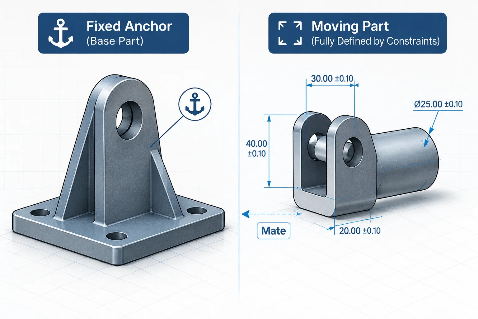
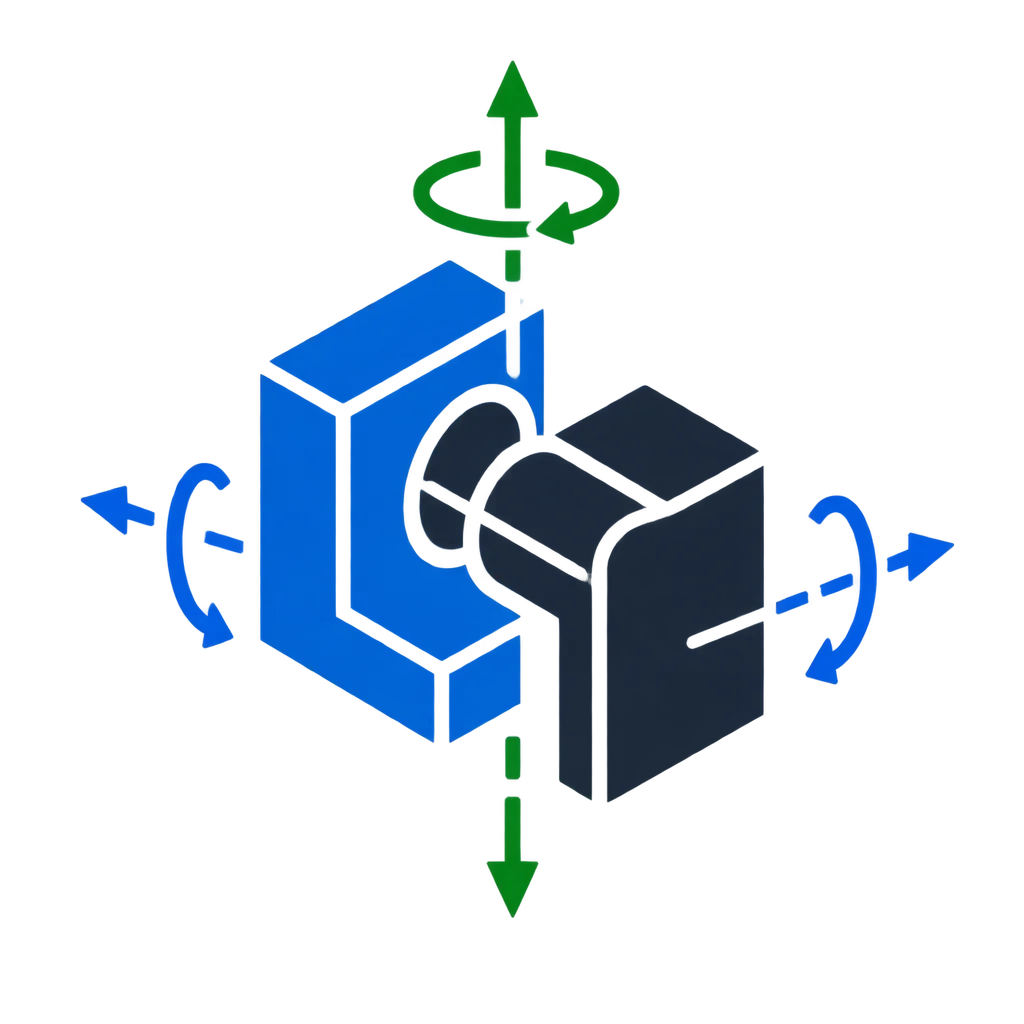
In parametric solid modeling, every unconstrained solid component starts with six degrees of freedom: three spatial translations along Cartesian vectors and three rotations around them. Mates exist solely to eliminate these degrees of freedom sequentially. A redundant constraint emerges when an applied relation attempts to restrict a translation or rotation that has already been fully governed by an existing mate or reference chain.
Geometric modeling kernels often tolerate redundant mates as long as both definitions remain numerically coincident to microscopic limits. However, parametric designs are dynamic. The moment an engineer alters hole spacing, changes an extrusion draft, or adds an angle offset in a sub-part, the solver can no longer satisfy both identical definitions simultaneously, turning harmless redundancy into catastrophic rebuild errors.
Clean mechanical assemblies do not rely on accidental geometric alignment. Every mate must have a single unambiguous mechanical job, eliminating ambiguity before numerical calculations ever begin.
How Assembly Solvers Signal Over-Definition
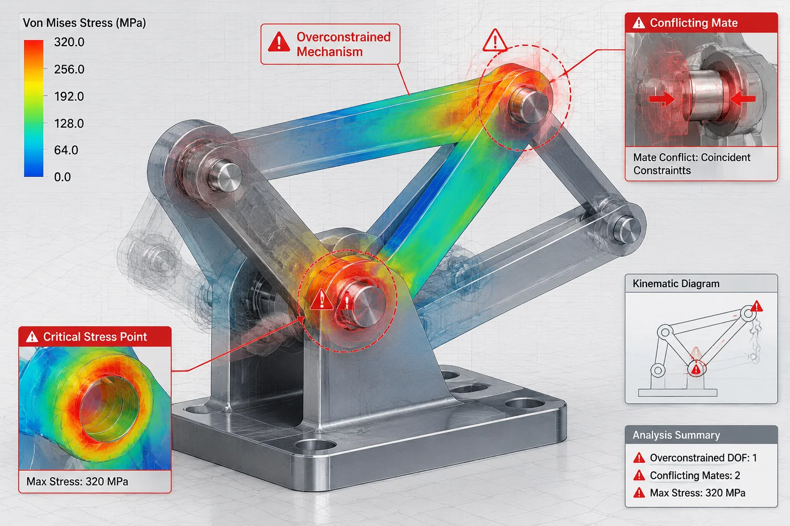
Modern CAD software continuously evaluates constraint matrices during model regeneration. When redundant or competing equations enter the matrix, the system reveals recognizable behavioral indicators throughout the feature tree and visual canvas:
- Yellow Warning Triangles: The constraint engine flags that a mate is consistent but unnecessary, signaling that removing it leaves the component fully defined.
- Dynamic Drag Latency: Dynamic collision detection and kinematic dragging crawl to a halt as simultaneous matrix paths demand exponential computational loops.
- Drawing View Inconsistencies: Assemblies load cleanly in lightweight mode but display exploded errors or displaced pins when fully resolved inside 2D drafting views.
Eliminating Redundancies for Robust Models
To maintain bulletproof assemblies, modelers should apply the 3-2-1 locating principle. Use a primary planar mate to eliminate three degrees of freedom (one translation, two rotations). Follow with a concentric or linear mate to lock two remaining translations, and conclude with an orientation relation for the final rotation. Fasteners, secondary dowels, and mounting brackets should utilize slot or clearance-friendly mates rather than duplicating rigid concentric relationships across multiple holes.