The Evolution of Fusion Assembly Logic
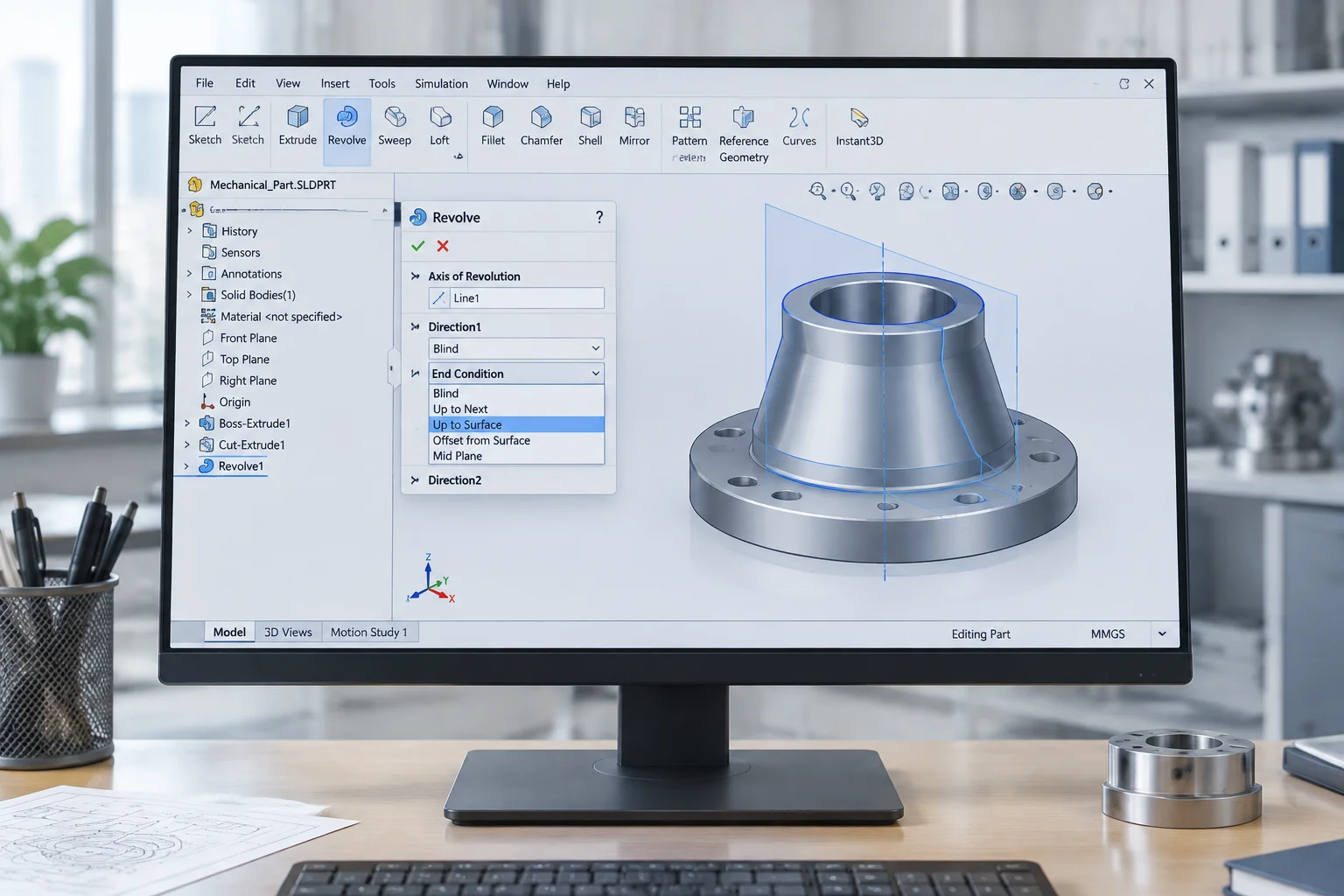
For years, mechanical design in Autodesk Fusion relied almost exclusively on joint origins. That approach delivered an elegant way to reduce degrees of freedom in a single step. Yet, when engineering teams imported legacy models or modeled intricate nested mechanisms, that single joint paradigm could feel rigid. It frequently forced designers to create arbitrary reference points just to mate two planar faces.
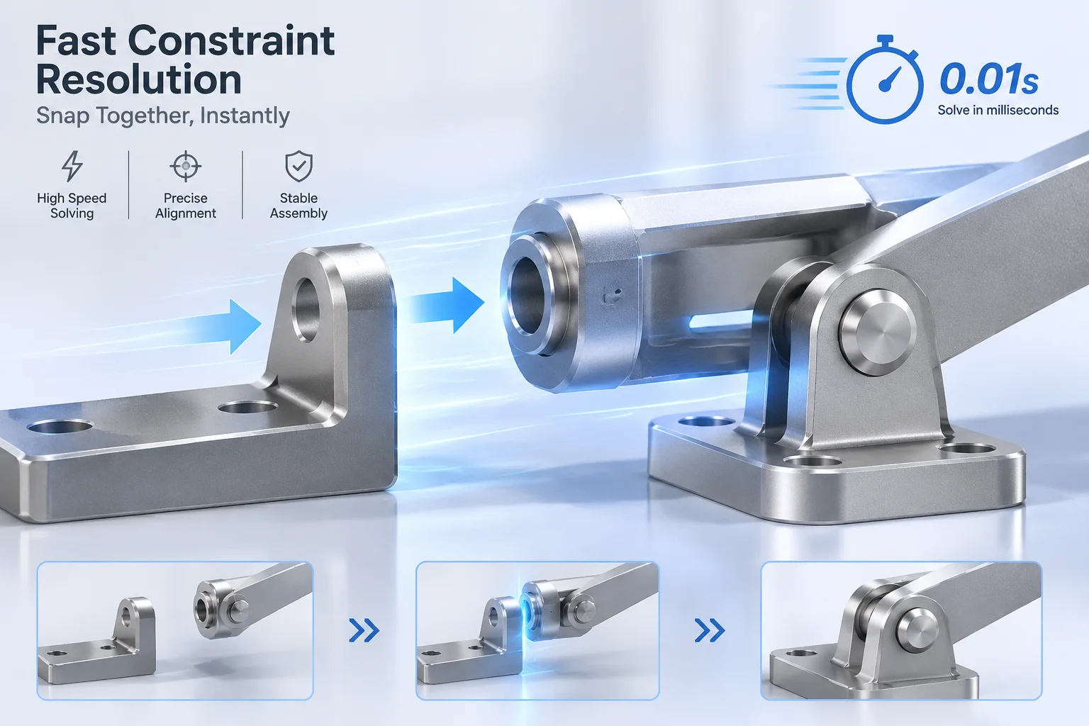
With the latest architecture release, the development team has implemented a dual-engine kinematic framework. Engineers can now define direct geometric constraints like coincident, concentric, tangent, and parallel alongside traditional joint pairs. This hybrid workflow drastically reduces model setup time across multi-station fixtures and robotic assemblies.
Elimination of Cyclic Redundancies and Solver Freezes
One of the most frustrating hurdles in parametric CAD is the silent solver stall. You position a pin inside a slotted link, define a limit, and suddenly dragging another component triggers an unresolved loop error. The upgraded solver addresses this directly by implementing a non-blocking graph traversal model.
Intelligent Path Disconnect
When two mates assert competing planar definitions, the software suspends only the redundant mathematical relation. It highlights the culprit in amber on the viewport instead of breaking the entire assembly tree into an irrecoverable error status.
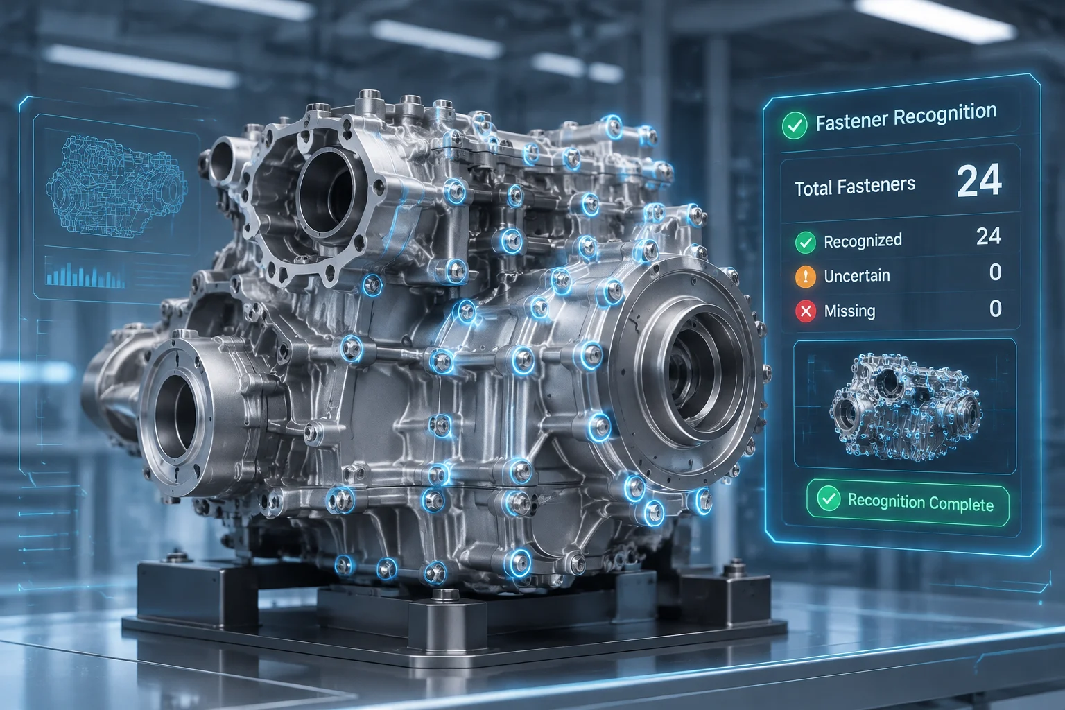
Furthermore, multi-threaded matrix operations now offload dynamic motion computations from the primary interface thread. While testing massive machine bases with over two hundred constrained fasteners, rotational motion remained fluid and predictable without freezing viewport rendering.
Practical Best Practices for Modern Constraint Trees
To get the most out of these expanded capabilities, engineering departments should refine their standard operating procedures. Relying entirely on raw surface constraints without grounding key components will still lead to unconstrained translation issues under dynamic loads. Establish systematic rules early in the design cycle:
- Ground the primary base casting or structural chassis before applying relational mates between subassemblies.
- Combine joint origins for kinematic drives while using direct planar mates for static mounting brackets.
- Audit the Degree of Freedom diagnostics panel periodically to catch lingering rotational freedoms on cylindrical pins.