Degree of Freedom (DOF)
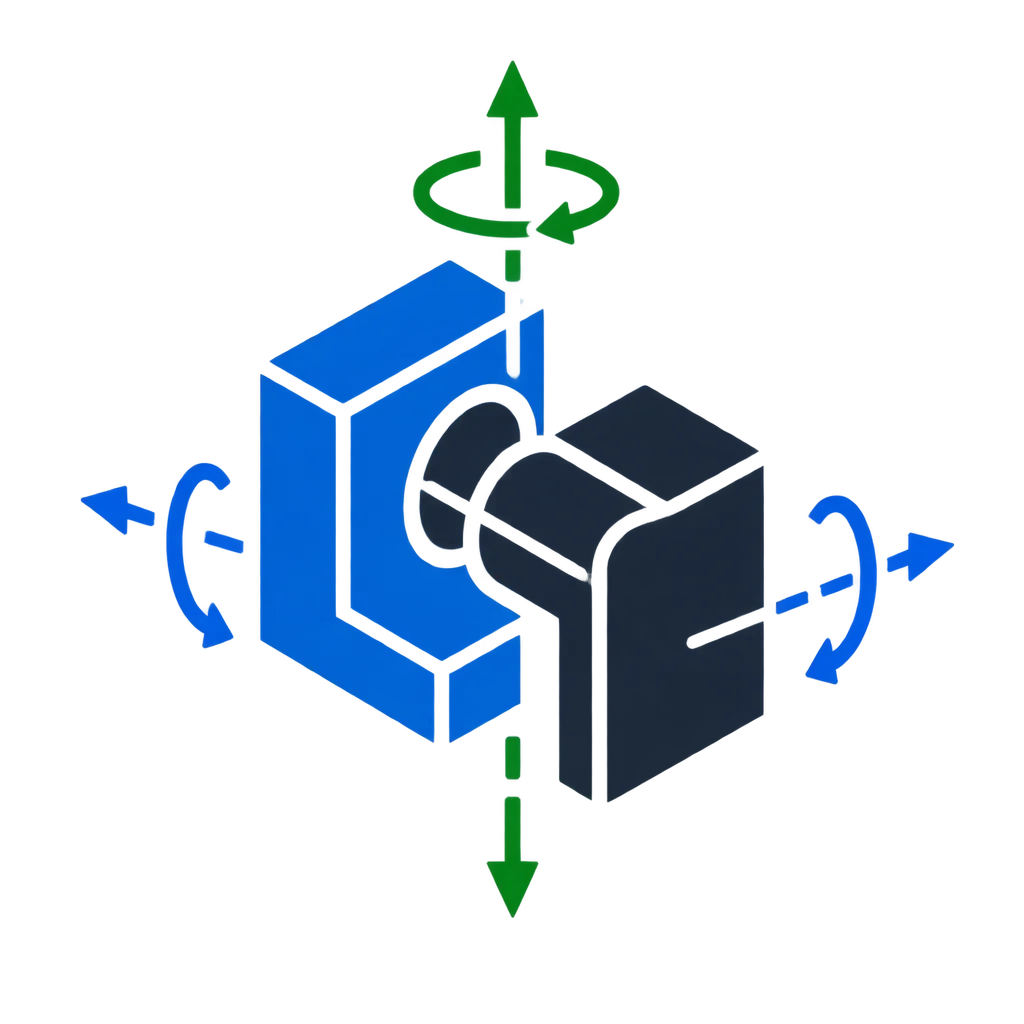
An independent translational or rotational axis along which a free rigid body can move in 3D space.
Explore assembly relationships, intended motion, overconstraints, and reference selection through independent mechanical design examples. MateIntent Notebook turns complex mating decisions into understandable engineering review cases.
“A good constraint preserves the motion that the design actually needs.”
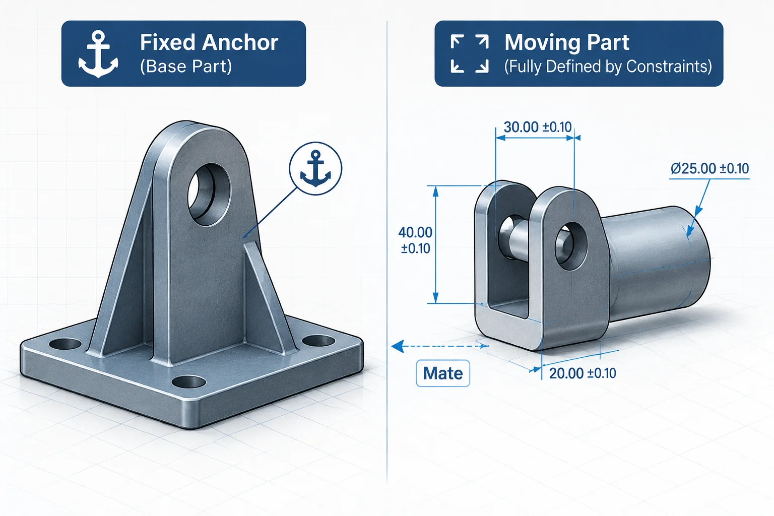
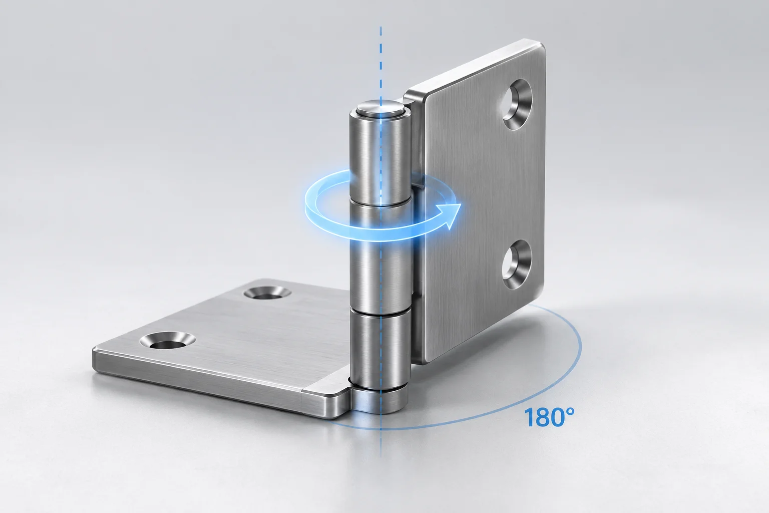
An isolated investigation of a three-component hinge: stationary base bracket, cylindrical axis pin, and pivoting linkage arm. The exact design intent requires strictly one rotational degree of freedom around the pin axis.
Yes. The base bracket is fixed. The axis pin is constrained concentrically and coincident to the base boss. The movable arm references only the axis cylindrical bore and its planar thrust shoulder. Exactly one rotational freedom remains about Z.
Follow this sequence for every single degree-of-freedom mechanism. No claims of successful resolution can be verified without solver logs and reproducible dynamic motion cycles.
Confirm solver counts exactly 1 remaining rotational freedom in the assembly diagnostic panel.
Drag component through full travel arc to verify no hidden lockups or unpredicted planar skew occurs.
Scan mate folder for duplicate coincidences and parallel locks introduced for temporary drawing views.
Force a deep model rebuild (Ctrl+Q) to guarantee no cached solver states mask broken edge references.
Essential diagnostic techniques to separate ground anchors from locked kinematics.
Evaluate mate topologies before releasing subassemblies. Receive a step-by-step PDF manual designed to diagnose overconstrained joints, unstable reference faces, and drifting degrees of freedom.
A systematic table of joint pairs verifying which coordinate translations and rotations remain deliberate and which are locked by duplicate mates.
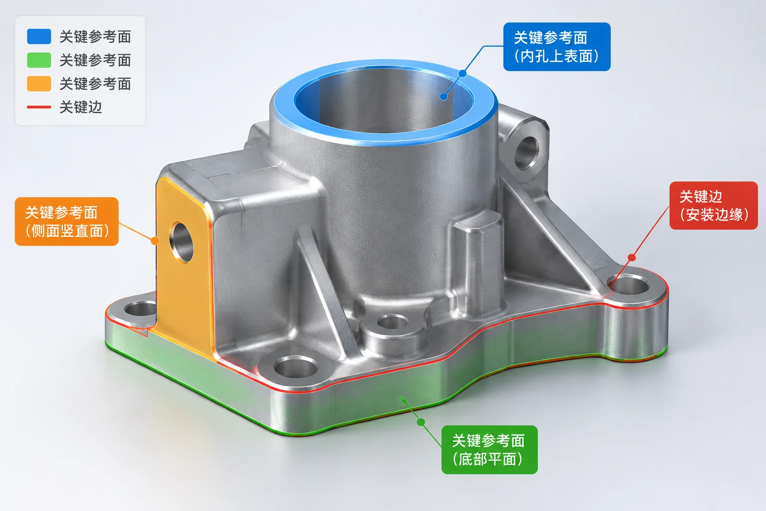
Definitive rules for anchoring mates to persistent design datums rather than volatile chamfers, fillets, or secondary draft faces.
Techniques to identify redundant concentric and coincident stacks before they cause regeneration slowdowns or silent assembly solver errors.
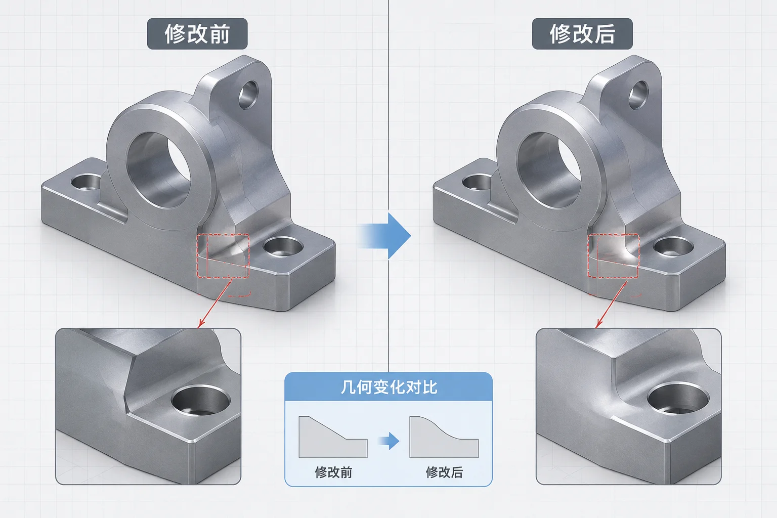
A targeted procedure to trace severed mate entities and repair dangling references following part remodeling or component replacement.
Direct engineering dispatch. Connect through WhatsApp to receive the complete PDF packet without registering or filling out web forms.
Clear, concise explanations of essential kinematic and mating concepts to help you diagnose CAD assemblies without guesswork.
An independent translational or rotational axis along which a free rigid body can move in 3D space.
A geometric constraint forcing two planar faces, axes, or points into the exact same spatial plane.
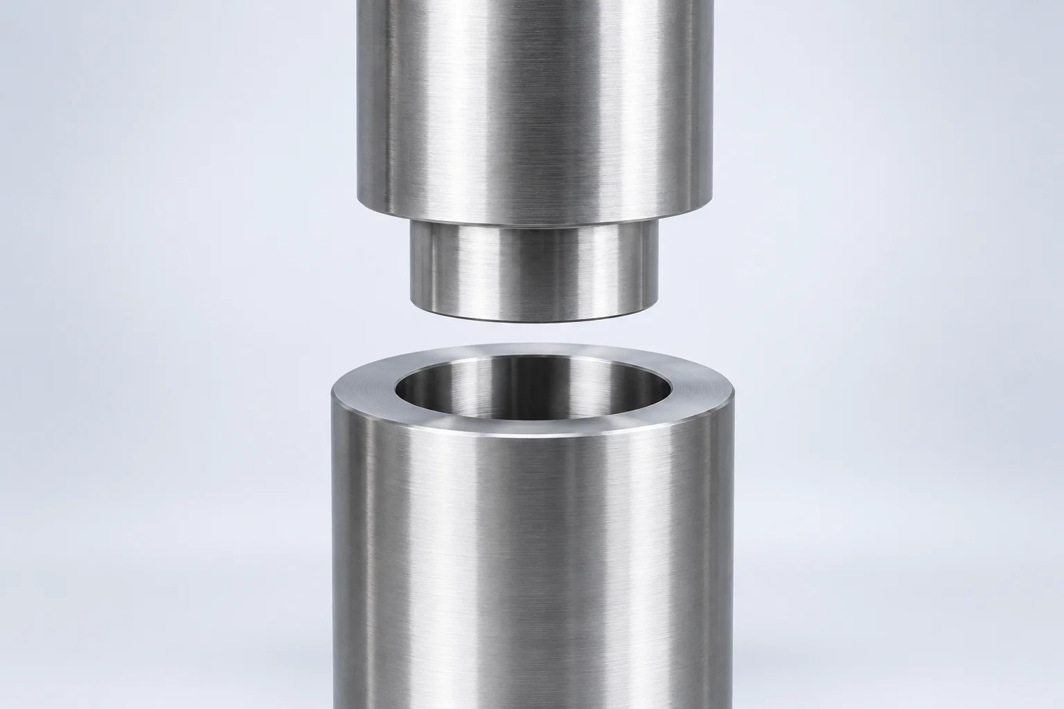
A relationship that aligns the centerlines of two cylindrical or conical features along a shared axis.
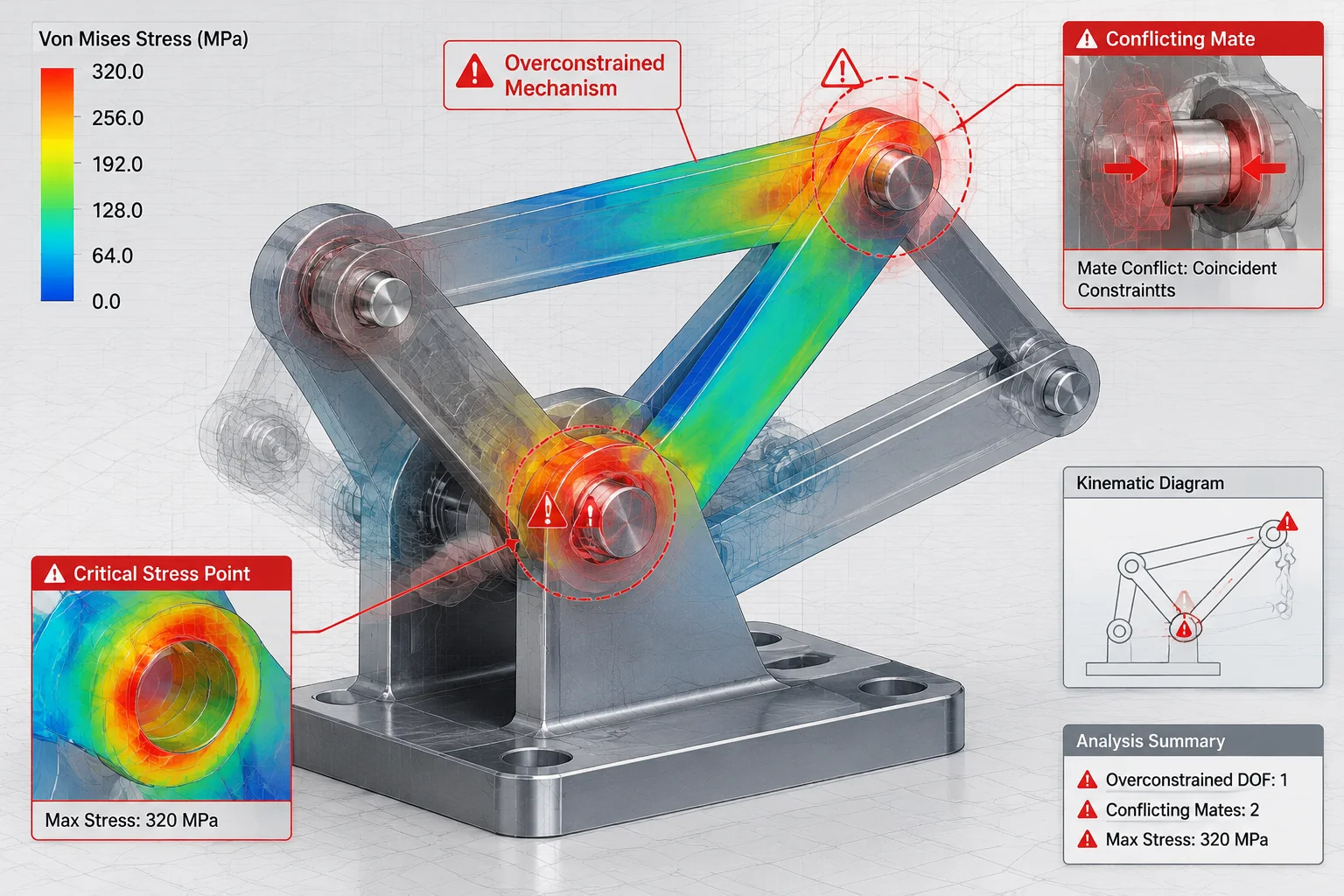
A conflict where multiple mathematical mates attempt to govern the exact same degree of freedom twice.
A solve calculation jump where an angular or offset mate flips 180 degrees during regeneration.
A base model locked permanently to the global origin without solving dynamic equations of motion.
Verify mechanical assembly expertise and constraint modeling integrity prior to contract sign-off, regardless of whether you collaborate with our team or an independent engineer.
Ask whether they mate to temporary chamfers, model edges, or functional coordinate datums and primary machined faces.
Aligns to main primary planes, central layout sketches, and functional contact planes rather than cosmetic fillet edges.
Mates directly to transient round edges or draft surfaces that break upon parametric regeneration.
Determine if they lock down every component arbitrarily or retain genuine rotational freedoms for kinematic checks.
Preserves the one planned rotation on pins and shafts while utilizing lock-rotation settings only on non-critical fasteners.
Freezes every component with 'Fix' anchors or parallel mates that obscure actual mechanism collisions.
Evaluate whether downstream parts cascade into missing reference errors or update cleanly according to design intent.
Positions brackets via layout datums; changes propagate predictably without red or yellow rebuild warnings.
Assembly explodes with dozens of orphaned mate errors due to tangled inter-part daisy chaining.
Inquire about their diagnostics procedure when multiple coaxial holes or planar faces compete for the same degree of freedom.
Uses concentric relationships paired with slotted or width mates, actively running assembly diagnostic solvers.
Forces coincident relationships onto duplicate parallel faces until the CAD solver generates hidden mathematical conflicts.
Ensure they know how solver performance degrades and how kinematic linkages behave inside higher-level mechanisms.
Maintains static modules as rigid groups, selectively enabling flexible behavior only for stroke analysis linkages.
Leaves all sub-assemblies in flexible mode indiscriminately, causing significant viewport lag and unstable solver cycles.
Establish whether deliverables are audited for suppressed errors, unconstrained under-defined components, or loose origins.
Performs a full force rebuild, sweeps for (-) signs in the feature manager tree, and documents motion extremes.
Hands over assemblies with suppressed broken mates or floating components hidden in collapsed sub-folders.
Detailed reviews of recent CAD releases, solver behavior changes, and best practices for defining component relationships.
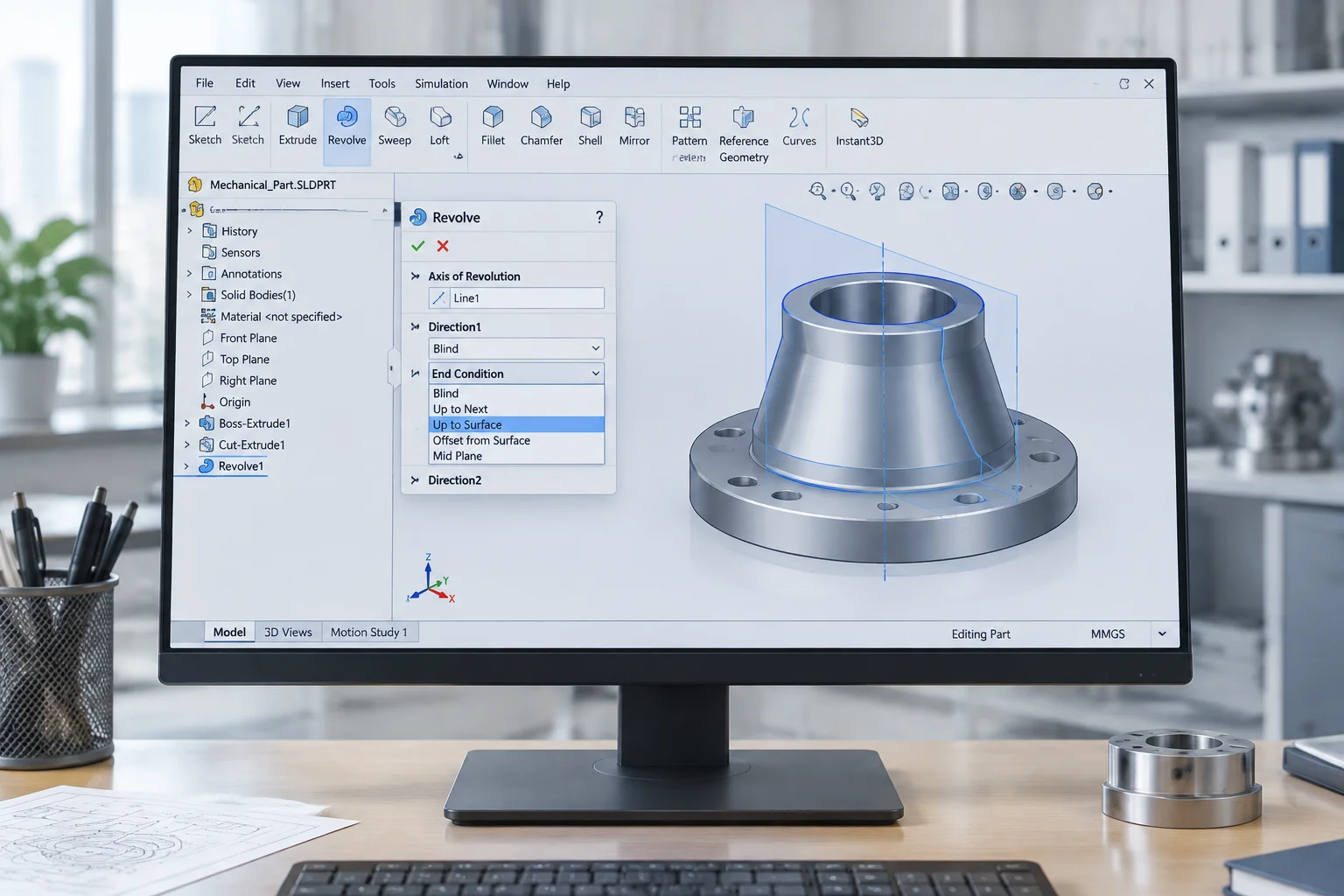
Evaluating flexible end conditions on revolve features and the preservation of rotational degrees of freedom in joint connectors.
New diagnostics for nested subassemblies and automated detection of redundant coincident mates during rebuilds.
Cloud-accelerated constraint calculation alongside improved visual cues for cylindrical and planar references.
Practical diagnostic methods to determine which component degrees of freedom must be restrained and which should remain unconstrained.
Analyzing kinematic pivots where leaving a rotational degree intact prevents binding during mechanism deployment.
Identifying overconstraining mates that inadvertently lock essential operational motion and cause assembly rebuild errors.
Comparing cylindrical centerline alignment against flat surface seating to balance axial tolerances properly.
Why referencing primary datum planes rather than editable part edges secures complex CAD models against broken links.